
Grid Following (GFL): what it is, how it works and differences from Grid Forming
Grid Following (GFL) is a control strategy used by grid-connected inverters and converters to synchronise with an existing voltage and frequency and, using that reference, inject the current needed to deliver the requested active and reactive power. Historically, it has been the control mode used by most inverter-based resources, such as solar PV plants, some modern wind generation and many BESS.
The key idea is in the name itself: a grid-following inverter “follows” the grid. It does not establish the system’s voltage and frequency reference on its own; instead, it measures the existing signal at its connection point, estimates its angle and frequency, and adjusts its output current to synchronise with it. From the grid’s perspective, it generally behaves approximately as a controlled current source seeking to meet active power (P) and reactive power (Q) references.
This approach works particularly well when the inverter is connected to a strong grid: a system in which voltage and frequency are sufficiently stabilised by synchronous machines, synchronous condensers, grid-forming resources or other elements capable of providing a robust reference. Problems arise when large numbers of GFL resources connect in areas with low short-circuit power, low inertia or a weak voltage signal: all try to follow a reference that may become increasingly unstable.
That is why Grid Following has become a central concept in the energy transition. Not because the technology is set to disappear — it remains effective, mature and widely used — but because growth in solar, wind and storage connected through power electronics makes it essential to understand when a system can operate mainly with inverters that follow the grid and when it needs resources capable of forming it.
How does a Grid Following inverter work?
Its operation can be understood as a control chain. First, the inverter measures the voltage at the connection point. A synchronisation system (usually a Phase-Locked Loop (PLL)) then estimates the phase angle and frequency of that voltage. This reference allows electrical variables to be transformed into a coordinate frame in which the controller can precisely regulate the current injected into the grid.
Using the power setpoints, the controller calculates how much current to deliver. Many designs use vector control along axes labelled d-q, allowing active and reactive power to be managed relatively independently. Finally, the inverter modulator controls the power semiconductors to produce the requested current.
NREL summarises this architecture in three fundamental blocks: PLL, power controller and current controller. The PLL synchronises the inverter with the grid; the power controller generates current references; and the current controller determines the modulation needed to meet those references. This explains a fundamental characteristic: to operate correctly, a GFL inverter needs a sufficiently well-defined voltage waveform to synchronise with. It is not simply a question of there being “electricity” on the grid; the signal must be stable enough for the synchronisation and control algorithms to interpret it correctly.
Key elements and characteristics of Grid Following control
Most GFL systems share a set of functions, although their specific implementation varies between manufacturers, technologies and connection requirements.
Phase-Locked Loop (PLL)
The PLL estimates the angle and frequency of the grid voltage. It enables the inverter to synchronise its current with the existing waveform and is one of the most characteristic elements of Grid Following control.
Current control
The inverter directly regulates the current it delivers to the system. From the grid’s perspective, a GFL inverter generally approximates a controlled current source whose output responds to internal power references.
Active and reactive power
P and Q setpoints determine the active energy exchange and reactive support the inverter must provide within its power, current and voltage limits.
External grid reference
GFL assumes that voltage and frequency are being established by other resources. It needs an already formed grid to synchronise and operate stably.
Current limits
Inverters have a much lower overcurrent capability than synchronous machines. During faults or major disturbances, the controller must prioritise the active or reactive current it can deliver without exceeding converter limits.
Fault Ride Through
Grid codes may require the inverter to remain connected during certain voltage dips or rises and provide a specified reactive current response during the disturbance.
Dependence on grid strength
The weaker the grid, the harder it may be for the PLL to maintain a stable reference. Short-Circuit Ratio (SCR) and other metrics are used to assess system strength at the connection point.
Fast power electronics response
Although it does not form the grid, a GFL inverter can change its current very quickly. This enables participation in power control, reactive support, power reduction and certain frequency responses, provided a stable reference exists.
Programmable control
Behaviour depends heavily on the control software. Two inverters with similar hardware can respond differently to a disturbance depending on their algorithms, parameters, protection systems and the operator’s requirements.
Where is Grid Following used?
GFL control is common in almost any resource connected through power electronics. In a photovoltaic plant, inverters convert the modules’ direct current into grid-synchronised alternating current. In wind power, particularly technologies with full- or partial-scale power converters, electronic controls regulate exported power. In a BESS, the Power Conversion System can operate in Grid Following mode to charge or discharge according to setpoints from an EMS or the operator.
It is also found in industrial installations, distributed generation, bidirectional chargers, HVDC systems and other converter-based resources. The term therefore describes a control philosophy for the electronic interface with the grid, rather than a specific energy technology.
In a utility-scale plant, the behaviour seen by the system also depends on more than each inverter’s individual control. The Power Plant Controller coordinates hundreds or thousands of units to meet power, power factor, voltage or reactive power references at the connection point.
Grid Following vs Grid Forming: key differences
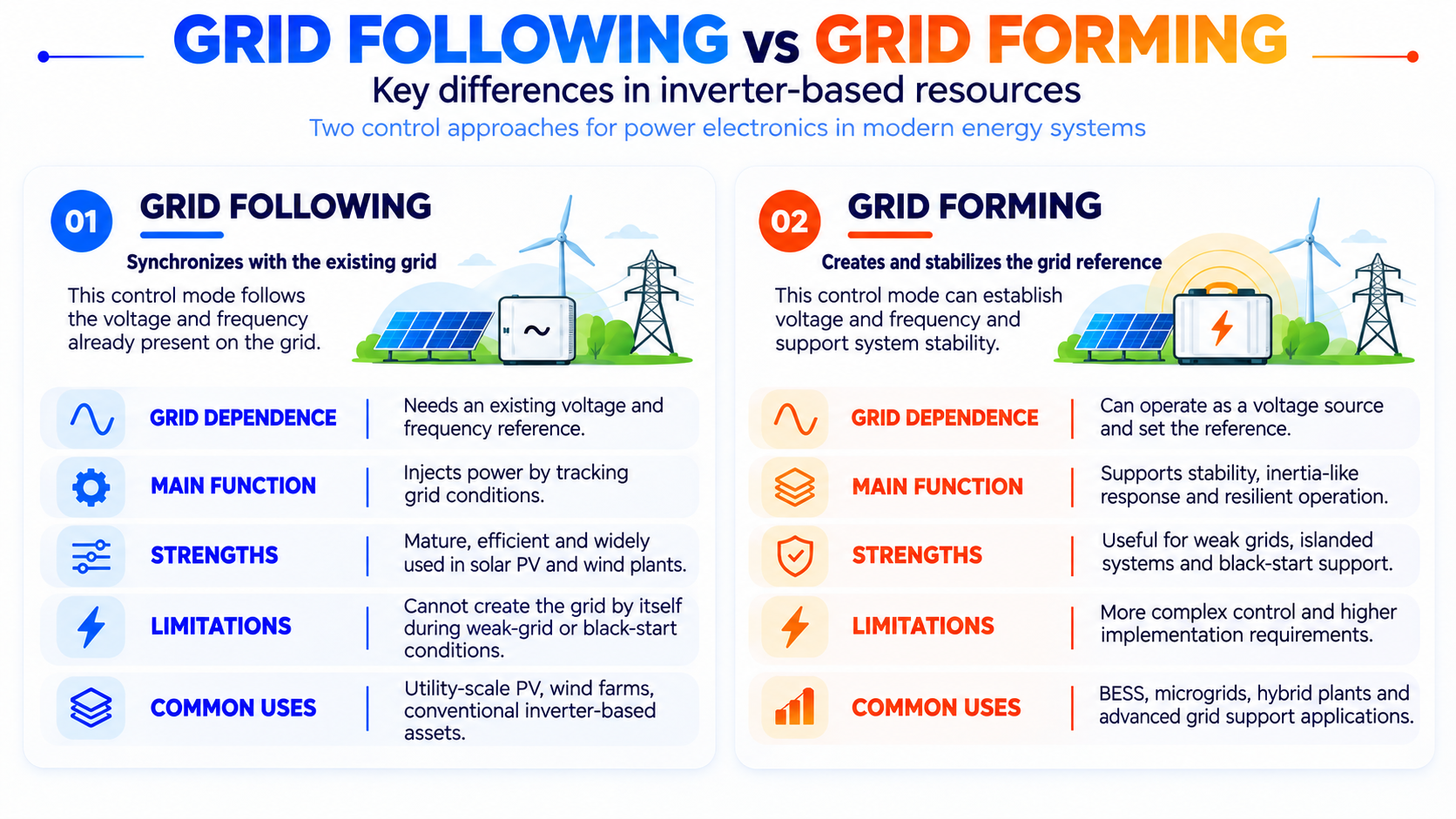
The difference is not simply that one concept is “new” and the other “old”. They represent two different ways of interacting with the grid. GFL measures an existing signal and adapts its current to it. Grid Forming (GFM), by contrast, controls a voltage and phase/frequency reference and can directly contribute to establishing the grid waveform.
| Feature | Grid Following (GFL) | Grid Forming (GFM) |
|---|---|---|
| Main controlled variable | Current / P-Q power | Voltage, angle and frequency |
| Synchronisation | Usually through a PLL | Does not rely on a conventional PLL to form the reference |
| Requires an already formed grid | Yes, in conventional operation | Can establish a voltage and frequency reference |
| Equivalent behaviour | Controlled current source | Controlled voltage source |
| Weak grids | May have stability limitations | Designed to provide greater robustness under these conditions |
| Black start / island operation | Usually cannot establish a de-energised grid on its own | Can be designed to energise and operate a grid without an external reference |
| Maturity and deployment | Very widespread and established | Rapidly expanding and subject to new technical requirements |
NREL explains the difference simply: Grid Following controls output current and depends on another source for synchronisation, while Grid Forming controls output voltage and can generate its own reference waveform.
Why can a GFL inverter have problems in a weak grid?
In a strong grid, connecting or disconnecting an inverter produces relatively small voltage changes at the connection point. The PLL has a robust reference, and the controller can assume that the grid is practically an ideal voltage source. As the system’s equivalent impedance increases and short-circuit power falls, this assumption becomes less valid.
In a weak grid, the current injected by the inverter can itself significantly change the voltage it is trying to follow. The PLL detects that voltage, adjusts its reference and changes the current, which then changes the voltage again. If the dynamics of the inverter, other converters and the grid interact unfavourably, oscillations, loss of synchronism or control instability may occur. The problem can worsen when several grid-following solar farms, wind farms or BESS are electrically concentrated in the same area. Each has its own controls, and all react to the same grid. Modern connection studies therefore examine not only load flow and short circuits, but also dynamic stability, control interactions and, in certain cases, EMT models.
NREL notes that GFL inverters work best when connected to a strong system and that, in relatively weak grids, PLL-based voltage tracking can lead to stability problems. The Short-Circuit Ratio (SCR) is one of the metrics traditionally used to characterise this strength, although systems with many inverters may need more sophisticated metrics and studies.
Grid Following during faults and disturbances
An inverter cannot deliver short-circuit currents on the same scale as a large synchronous machine. While a conventional generator can supply several times its rated current during a fault, power electronics are limited by the thermal and electrical capabilities of their semiconductors. This significantly changes system protection and dynamic response.
However, low fault current does not mean a lack of control. A modern GFL inverter can detect a disturbance within fractions of a cycle and execute programmed strategies: remain connected, reduce active power, prioritise reactive current, limit total current or disconnect if certain thresholds are exceeded. Requirements for Fault Ride Through in grid codes determine how the asset must behave during voltage dips, overvoltages, frequency deviations and other conditions. This response is particularly important for large installations. If hundreds of MW of inverter-based generation disconnected simultaneously in response to a moderate disturbance, the initial fault could be amplified. Coordination between protection systems, inverter control and connection requirements is therefore an essential part of integrating power-electronic resources.
Can Grid Following support frequency and voltage?
Yes. Saying that a GFL inverter “follows” the grid does not mean it is passive. It can adjust reactive power to support voltage control, follow active power setpoints, limit exports, participate in curtailment, apply Volt-VAR or Volt-Watt curves, and change active power in response to frequency deviations.
It can also provide fast responses if it has energy headroom. A GFL BESS, for example, can increase or decrease its power very quickly. A solar plant can reduce power almost immediately and, if it operates with headroom, even temporarily increase generation within the available solar resource. The difference from Grid Forming lies in the reference mechanism. GFL performs these functions by first measuring the existing voltage and frequency and responding relative to them. GFM participates directly in creating and stabilising that reference.
Does this mean Grid Following is an inferior technology?
No. Grid Following is a very mature, efficient and widely deployed strategy. It can perform excellently in strong grids, and automatically converting all inverters in the system to Grid Forming would make little sense. The aim of current developments is to determine which combination of GFL, GFM, synchronous machines, synchronous condensers and other resources provides sufficient stability at the lowest cost.
Indeed, a system can operate with large numbers of GFL resources provided there is a sufficient voltage reference, grid strength and stabilisation capability. In microgrids and systems with very few synchronous generators, some inverters can operate as Grid Forming while others continue as Grid Following. NREL illustrates precisely this coexistence approach. The relevant question is therefore not an absolute choice of “GFL or GFM”, but how much grid-forming support each area needs and which assets can implement it most efficiently.
Grid Following, BESS and the future of Europe’s grid
Storage is at the centre of this evolution because a BESS can use practically the same power hardware with different control philosophies. A PCS can operate in GFL mode in a conventional project and incorporate Grid Forming capabilities if its hardware, firmware and design allow. Control specifications are therefore becoming as important as MW power ratings or MWh energy capacity.
In Europe, ENTSO-E published its Phase II technical report on Grid Forming requirements in November 2025. This work is linked to the evolution of the Network Code on Requirements for Generators and aims to prepare a system increasingly dominated by non-synchronous generation and storage. ENTSO-E considers these capabilities essential to maintaining the stability and resilience of Europe’s future grid. This does not mean Grid Following will disappear. The most likely outcome is a hybrid grid in which millions of GFL resources coexist with sufficient GFM resources and other support technologies. The required proportion will depend on each area’s strength, grid topology, generation mix, protection response and the stability criteria defined by each operator.
What to assess in a project with Grid Following inverters
For a developer or investor, knowing that a manufacturer uses Grid Following control is not enough. The specific technical requirements of the Grid Connection, the expected SCR, future grid development, the concentration of other inverter-based resources, and P/Q, voltage, frequency and Fault Ride Through requirements must all be assessed. Manufacturer-supplied simulation models are also important. In strong grids, RMS studies may be sufficient for many assessments. Where grid strength is low or converter interactions are high, EMT models may be needed to represent the PLL, current loops, limiters and protection systems in greater detail.
Finally, the scope for upgrades must be reviewed. An inverter with a flexible architecture, updatable firmware and validated models may have an advantage over equipment whose control behaviour is difficult to change during the asset’s 20- or 30-year life. As grid codes evolve, the capabilities required of inverter-based resources are likely to become more sophisticated. Grid Following will therefore remain a fundamental part of the power system. Its main limitation is not that it “does not work” with renewables, but that it needs a sufficiently robust grid reference to follow. Understanding this dependence is essential to designing grids with high solar, wind and BESS penetration without compromising stability.